’73 TCS Federal Lotus Europa
Body
Removal Notes
Disclaimer: I used Phil Ethier’s “Europa Body
Removal” email as my guide and took notes as I went. In a couple of places I quote him. In a number of cases the configuration of my TCS was not stock,
and so some of my steps may not match your car (and there are some TCS vs. S2
differences). This worked for me, as
written, but your mileage may vary and you should use your own judgment where
my approach seems wrong. I am an
amateur mechanic and new to Lotus repair.
Russ
NOTA
BENE: All nut and bolt measurements
given are tool size, not actual bolt size.
1 Removed front trunk lid
1.1
Removed spare tire
1.2
Removed the 2, ½” lid
retaining bolts, one from each side
1.2.1
Each bolt had a washer
between the bolt head and the trunk lid
1.2.2
Each bolt had a rubber
washer between the trunk lid and the body
2 Removed rear deck lid
Deck lid is bolted
to two hinges that are themselves mounted to the exterior body. I removed the lid from the hinges and left
the hinges attached to the body.
2.1
Removed 2 top nylock
7/16” nuts from each hinge, with fender washers between nut and deck lid
2.2
Removed 2 bottom nylock
7/16” nuts from each hinge, with fender washers between nut and deck lid
3 Removed wheels and placed car on jack stands.
4 Removed Air Horn (original?)
4.1
[The horn was not
working and the ground wire from the air pump was not connected]
4.2
A/H was mounted with 2,
½” through bolts, with fender washers between the nuts and the body panel. Bolt heads on the top of the A/H bracket,
nuts and washers under the car. Pump was mounted with circular clamp that is
itself mounted to the trunk bulkhead that holds the radiator.
4.3
Removed A/H by removing
the 2, ½” nuts and bolts
4.4
Disconnected positive
lead from air pump (bayonet connection, blue wire) and labeled it as such. Ground was not connected; not sure where it
goes.
4.5
Removed air pump by
pulling out of the circular clamp (it was a light press fit).
5 Removed rear “Trunk” tray
5.1
[Air cleaners is
mounted on this tray. I left it in
place for the time being.]
5.2
Loosened clamp holding
air cleaner hose to carburetors and pushed hose off carbs.
5.3
Tray then lifted
out. [Two nuts and bolts that should hold the tray to the frame were missing.]
6 Removed radiator
Note: The chassis closing plate was missing. If it had been there, I would have removed
it at this time. As Phil points out,
once the closing plate is removed, be careful to not place a load on the front
of the body. The closing plate is a
structural member that helps support the front of the body. If you overload the front, the fiberglass
will crack.
6.1
Drained fluid
6.1.1
Removed sensor ground
wire that goes through hole in trunk, by radiator, to center of front frame,
secured by SS Phillips screw.
6.1.2
Loosened the upper hose at the radiator end first, and drained down as
far as possible by lowering the hose end into a bucket in the nose.
6.1.3
Placed a catch basin under the drain hole in the bottom of the luggage
compartment. (At then end of this
process I had to clean the residual coolant from the luggage compartment.) Phil did this differently:
“There does not seem to be a
drain anywhere, so removing the radiator hoses is the only way. I took off the
upper hose at the radiator end first, and drained down as far as possible by
lowering the hose end into a bucket in the nose. I cut up an antifreeze bottle
to make a big flat pan to fit under the lower radiator hose connection. Any
coolant you spill goes out the drain hole in the nose, so have a pan under the
car to catch it.”
6.1.4
Pulled temperature
sensor sending unit out of press-fit rubber grommet. Additional fluid drained.
6.1.5
Loosened the lower hose at the radiator end and drained into luggage
compartment.
6.1.6
Lowered front of car
with jack and released radiator cap on overflow tank in engine compartment to
get as much remaining coolant as possible.
6.2
Removed 3, 7/16”
radiator mounting bolts. Top is
through-bolt with fender washer and nut on reverse side. Two bottom fasteners are studs attached to
radiator with nuts and fender washers on obverse side.
6.2.1
Both studs were
corroded and snapped off. Radiator shop
will put in new studs.
6.2.2
Body holes are much larger than stud size and there
were no rubber grommets under the radiator.
May require repair/modification.
6.3
Disconnected 3
electrical leads from radiator fan
6.3.1
Ground wire bolts to
stud.
6.3.2
Remaining two wires
have bayonet connectors. Yellow wire
goes to the lower left, facing the radiator.
I labeled the wires.
6.4
Removed fan from
radiator
6.4.1
Removed 2, 7/16” nuts,
top right and left, with washers. Studs
are on radiator.
6.4.2
Removed 1, 5/16” through
bolt, washer and nut.
6.5
Tried to remove stone
screen from back of radiator.
6.5.1
Three of six screws
came off, the others were corroded/frozen.
Radiator shop will fix.
6.6
Removed press fit
grommet for temperature sensor sending unit from radiator end cap.
7 Removed Battery
7.1
Battery attachment is not stock. The battery
is sitting on a wooden tray that is loose on the fiberglass tray. The latter is damaged. A simple metallic heat shield has been
attached to the fiberglass tray, engine side (see Photo 1). New holes have been drilled in the
fiberglass tray and new, shiny “J” bolts have been installed. One original black “J” bolt was loose in its
original hole. The “J” bolts secure an
aluminum plate across the top of the battery.
The plate sits on a rubber strip (see Photo 2).
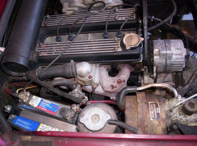
Photo
1. Battery attachment, as purchased.
7.1
Remove two 7/16 nuts
and lock washers from “J” bolts (nuts and washers are stored on “J” bolts.
7.2
Disconnect leads. Ground cable is red and attaches to the top
Eng/Trans bolt, front side. Alternator support bracket is on rear side of same
bolt (see Photo 3). Positive cable
(also red) has a joint in the middle to ease body removal. I separated the cable at the joint (using
two 9/16” wrenches) and put the cable piece with the battery parts.
7.3
Battery had to be
pulled out on end to clear body work.
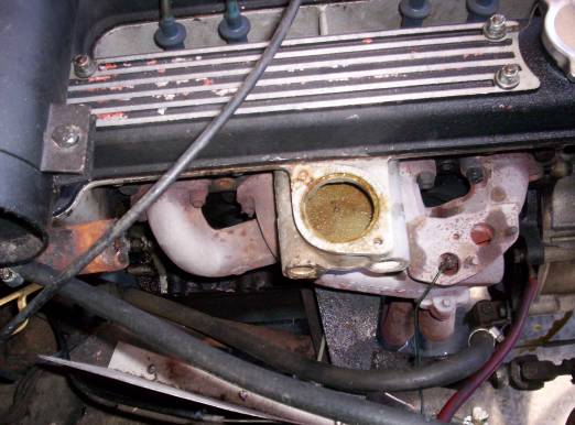
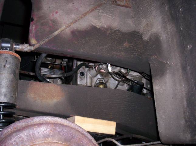
Photo 2. Engine from drivers side after removal of heater control and thermostat. Note vertical aluminum heat shield screwed to fiberglass battery pan.
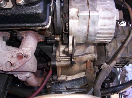
Photo 3.
Ground wire attaches to Eng/Trans bolt, as does the alternator bracket.
8 Remove heater control, thermostat, and temperature
sensor
8.1
Disconnect heater hose
from control housing.
8.2
Release
heater-control-cable wire from clamping screw and release cable housing from
clamp (5/16”). Note that heater control
can be rotated off the main housing. It
is a press fit and has some missing “teeth.”
It may not be on in the right orientation.
8.3
Unscrew heater control
housing from cylinder head.
8.4
Disconnect temperature
sensor wire from sensor on thermostat housing.
Unscrew temperature sensor, then unscrew sensor fitting from head.
8.5
Remove thermostat cover
from head (2, ½” bolts) and remove thermostat.
8.6
Remove thermostat inlet
hose from main water line, which itself disappears down into the body
9 Remove coolant tank lines
9.1
Removed small diameter
overflow hose that connects to the main water line.
9.2
Removed short, medium
diameter hose from bottom of tank. It
connects to radiator fill line. I cut
it in half to ease removal. For reassembly
it should be put on the tank prior to reinstalling the body and should be
watched for alignment when the body is lowered. Alternatively, the tank must be removed from the body prior to
reattaching the body.
10
Remove throttle and
choke linkage (see Photo 4)
10.1 Loosen 5/16” throttle cable nut (center of
carb-to-carb linkage rod) and pull wire free. Cable housing is not attached to
anything and whole cable now can be pushed out of the way.
10.2 Loosen 5/16” choke cable nut on front carb and pull
wire free. Cable housing is held in
place by a spring clamp on the top of the carb. Choke cable can now be pushed out of the way.
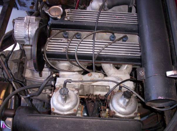
Photo 4. Passenger side showing throttle and choke
cables.
11
Remove brake sensor
wire.
11.1 On the frame, drivers side, towards the front of the
engine, adjacent to the dip stick, there is a brake line junction.. It has two bayonet connectors on it. The front connector is bent and takes the
double wire lead. The back connector,
which is straight, takes the single wire lead.
12
Removed misc. engine
compartment electrical leads.
12.1 Transmission back-up light wires (part of alternator
cable) connect via bayonet. Same color
wires, so assumed no polarity issue.
12.2 Alternator cables fit with unique plugs; no refit
issues
12.3 Solenoid has two bayonet connectors. I labeled them for reattach location. The third connector is a stud with 7/16”
nut. Two large power cables were
connected. Both are labeled.
12.4 Coil has three leads with bayonet connectors. I labeled them Coil L, Coil R, and Coil Mid
based on their position.
12.5 I disconnected the coil high voltage lead that goes
to the distributor.
12.6 Disconnected low voltage lead to distributor from its
bayonet connector. So labeled
12.7 Disconnected ground to chassis from alternator
cable. It is attached to the top ½”
bolt that holds the 450 brace to the main frame.
13
Remove radiator hoses
from front chassis tubes.
13.1 Photo 5 shows orientation, chassis to the left. Note upper hose is shorter.
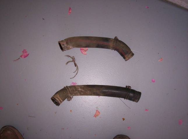
Photo 5. Front radiator hoses. Left = chassis. Top hose is shorter.
14
Remove heater hose from
body tube in engine compartment.
14.1 Heater hose runs from heater control on cylinder head
down below the engine to connect to a tube the runs into the body (see Photo
7). Heater control end was removed in
step 8.1, above.
14.2 Photo 6 shows the heater hose at the top with the end
that connects to the body tube on the right.
The tie wrap was loose and its purpose unknown,
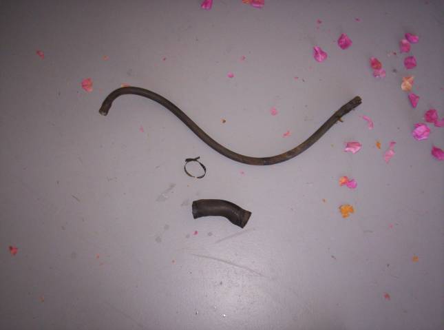
Photo 6. Heater hose and lower engine block to
chassis tube hose.
15
Removed lower engine
block coolant hose
16
Removed connecting hose
from coolant reservoir tank tube to main chassis return tube (see Photo 7)
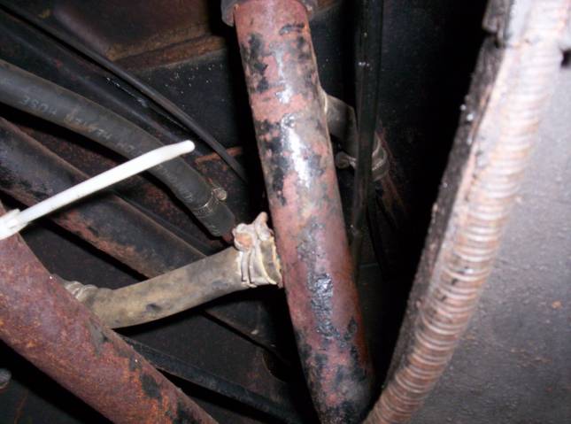
Photo 7. Coolant tank connecting hose and heater hose
in place
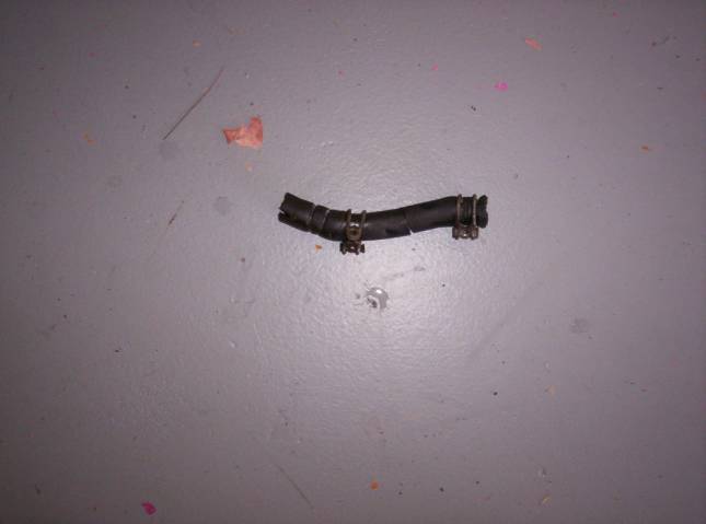
Photo 8.
Coolant tank connecting hose
16.1 Coolant tank has a short hose that connects it to a
metal tube that runs down below the engine.
That metal tube is then connected to the main lower radiator line with a
short hose that connects to a branch of the main chassis coolant tube. The lower part of this arrangement is shown
in Photo 7.
16.2 I had to cut the hose to get it loose. Hose is shown in Photo 8.
17
Remove seats
17.1 Push the seat all the way back on the runners.
17.2 Two ½” bolt heads are now accessible. They are in the runner channel, at the
front, one on each side. Remove
both. A short ½” box end wrench is the
easiest tool. Note, there is also a ½”
nut on the seat runner itself. This
does not need to be removed.
17.3 Slide the seat all the way forward. It will come off the runners. The two back ½” nuts can now be removed and
the seat tilted out of the car.
18
Remove inboard seat
belts
18.1 Remove 11/16” bolts that retain the inboard seat belt
fixture. Belt fixture stays in car
because it is wired to the interior harness (presumably for the seat belt
lock-out feature required by the U.S.)
19
Remove Pedal Assembly
(see Photo 9)
19.1 Remove cotter pin from brake pedal pin and remove
brake pedal pin and two washers (Cotter Pin/Yoke/Washer/Yoke/Washer/Pin head)
19.2 From underneath car, behind master cylinder, remove 4
7/16” nylocks and fender washers.
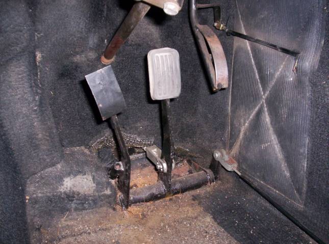
Photo
9. Pedal assembly before removal.
20
Remove clutch cable.
20.1 Cable housing ends are press fit into brackets at
passenger tunnel and in engine compartment on frame.
20.2 Remove cotter pin from inboard side of clutch pedal
extension lever and remove pin.
20.3 Pull clevis free from clutch lever on bell
housing. Remove jam nuts and clevis.
20.4 Pull cable housing free from tunnel in interior (pull
up edge of carpet) and pull cable assembly complete from engine compartment and
remove.
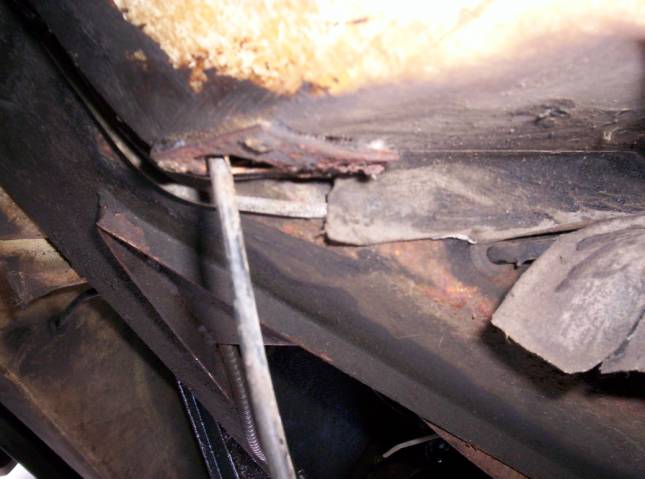
21
Disconnect handbrake
lever mount
21.1 The instructions said to remove the throttle pedal,
but I did not.
21.2 Pull large rubber stopper in luggage compartment.
21.3 Remove ¾” bolt from top of lever. (See Photo 10.)
21.4 Wrestle brake cable free from lever, push back into
frame.
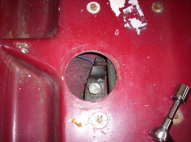
Photo 10. Handbrake
brake cable and lever
22
Pull throttle cable
down to body
22.1 Throttle cable runs from lower driver side body hole
(see photo 11), up over engine to passenger side where it connects to the
center of the dual carb linkage.
Throttle is “held” in place on the frame, near where it enters the body
(see Photo 12) by a soft plastic loop.
22.2 I pulled it down out of the way, but did not pull it
out of the body.
Photo
11. Throttle and Clutch cable hole in
body.
I
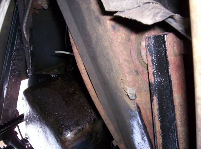
Photo 12. Throttle cable plastic loop that positions the cable prior to its
going up over the engine.
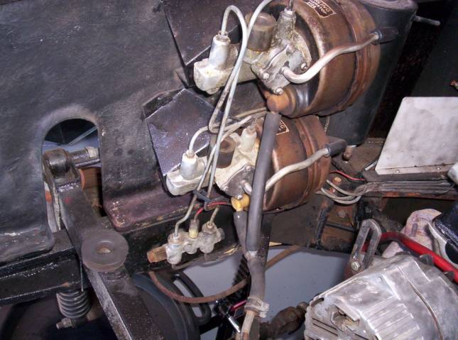
Photo 13. The brake fluid distribution block on the
frame below the vacuum reservoirs.
8 Remove master cylinder
7.4
Drain brake fluid (I
disconnecting the brake lines at the distribution housing (7/16”) in the engine
compartment (see Photo 13) and then pumped the brake.)
7.5
Remove the brake sensor
wire from the distribution block (Photo 13) by pulling the red wire with black
stripes from its bayonet connector.
7.6
Disconnect the two
7/16” brake lines at the vacuum reservoirs that are a hard link between the
body and the frame. Gently bend them
out of the way.
7.7
Remove the two ½”
nylock nuts from the master cylinder base from under the front of the car. Top nut requires the longer box end wrench
because of close quarters. Based on
Phil’s description, I assume that the S2 has four mounting nuts
10.3 Remove clevis from brake pedal linkage end, in
passenger foot well, by loosening the jam nut and unscrewing the clevis.
10.4 Pull master cylinder assembly from car and drain.
11
Remove Steering Column
and Steering Rack
11.1 The steering rack had to be removed to get at the
pinch bolt that holds the lower, inner steering column in place. The pinch bolt is inside the frame and while
it can be reached with a box end wrench, it was too tight for me to loosen that
way. I understand that the design for
the S2 is slightly different and that the pinch bolt can be released. Phil’s notes just say “Remove steering
column.”
11.2 I first followed the manual’s instructions for
removing the Inner Column (Europa Manual section H.3)
11.3 Free Both Tie Rods (Started with the driver’s side).
I removed the disc brakes at this time to make this easier. I knew I was going to rebuild them anyway, so no reason not to take them off now. This is not necessary to remove the Tie Rods
11.3.1
Remove wheel bearing
dust cover by wiggling it out with a large pair of vice grips.
11.3.2
Remove cotter pin and
castellated nut.
11.3.3
Remove 7/16” brake line
connector from caliper. Brake fluid has
been previously drained.
11.3.4
Remove 2 5/8” caliper
bolts from back side of caliper.
Breaker bar was required and the top bolt is blocked by hard brake line,
which needs to be removed or gently bent out of the way.
11.3.5
Withdraw caliper and
remove disc and hub.
11.3.6
Load the front
suspension so that it is not putting tension on the tie rod.
11.3.7
Remove top two, ½”,
bolts from brake shield.
11.3.8
Loosen front, lower
9/16” bolt by loosening the nylock nut on the reverse side. Don’t remove until tie rod is loose.
11.3.9
Remove rear lower 9/16”
bolt.
11.3.10 Bracket shield is now loose and can be moved around
to miss the pickle fork.
11.3.11 Once the tie rod is loose (see below) finish removing
the front, lower 9/16” bolt and extract the steering arm.
11.3.12 Using pickle fork, break tie rod loose from steering
arm
11.3.13 Repeat for passenger side.
11.4 Remove steering rack mounts
11.4.1
Steering rack is held
in place by two split clamps that bolt to the frame (see Photo 16). There is a left and right mount and they are
marked differently as pairs. Note which
is which on removal
11.4.2
Remove four 7/16” rack
mount bolts.
11.4.2.1
Top two bolts have the
head inside the frame and the nuts are nylock.
As a result, as soon as the nylock nuts are broken, the bolts begin to
rotate. The bolt heads can be reachable through the access ports (remove the
rubber plugs). Photo 17 shows the loose
bolts protruding from the frame after removal of the rack.
11.4.2.2
The two lower bolts go
into captive nuts in the frame and can be simply unscrewed.
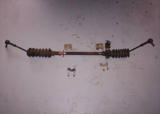
Photo 16. Steering rack and mounting clamps.
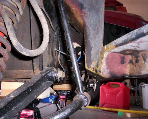
Photo 17. Loose steering rack mount bolts protrude
from frame.
11.4.3
Pull steering column
U-joint out of frame (remember this is why we are doing all of this!)
11.4.4
Remove upper ½” bolt
that holds inner steering column pinch bolt.
Use wedge to open pinch clamp and remove splined end of inner steering
column.
11.4.5
Withdraw steering rack,
with finagling, through passenger side opening between the roll bar and the
spindle. When ½ way out, pull rack
completely in the direction of the driver’s side.
12
Disconnect fuel line
12.1 Loosen clamp on fuel line at fuel pump; pull fuel
line free.
12.2 Drain gas tanks if necessary by lowering the fuel
line below the tank level, the gas can be saved in a gas can. (The drain plugs
at the bottom of the tanks are hard to use because the gas does not flow
straight down but sprays as it comes out, picking up dirt.)
12.3 Release gas tank cross feed from driver’s side and
pull through frame to passenger side.
13
Pull carbs, with
flanges by removing three, 1/2” nuts per carb.
See Photo 18 for parts arrangement.
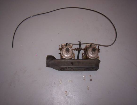
Photo 18. Carbs off car with nuts and washers.
14
Remove center console
14.1 Arm rest pad pops out (blind fasteners).
14.2 Unscrew shift knob.
14.3 Remove four screws holding shift boot to console
(probably not stock; original was a press fit but console has warped.
14.4 Two 7/`6” nylock nuts hold choke/heater bracket through the frame. Removal required holding
the bolt head under the console. Bolts
are held in place with undercoating and must be pushed down to remove . Bracket needs to be pushed down into the
frame tunnels, clear from body. Note
that there are two spacers on the back of the bracket that hold the bracket
above the body
14.5 Remove ash tray and unscrew two Phillips screws that
hold ash tray mount.
14.6 Remove “beauty” Phillips screws from the front of the
console on each side, two total.
14.7 See Photo 19 for console parts arrangement.
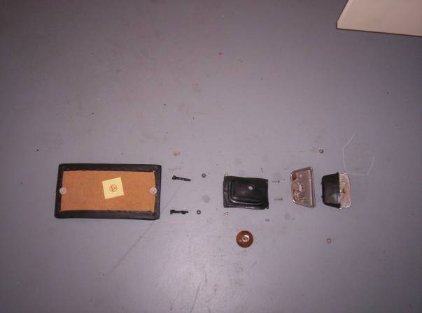
Photo 19. Console parts arrangement.
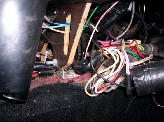
Photo 20. Dash bracket to frame bolt.
18
Remove dash bracket to
frame nuts. See Photo 20.
18.1
Remove 9/16” bolt from
each side of console, under dash. Wow,
how are we going to align this when we put the body back on?
19
Remove Front Body
Retention Bolts
19.1
Remove rubber plugs on
each side in the luggage tray in the nose.
19.2
Remove the 9/16” bolts
through the holes. The associated
nylock nut and washer are in the shock tower.
20
Remove Rear Body
Retention Bolts
20.1
Remove the two (one on
each side) 9/16” bolts, at the rear of the engine compartment adjacent to the
end of the transmission, with washers and nylock nuts under the frame.
21
Free speedometer cable
21.1
Speedo cable is press
fit into transmission end (Is this right?
Shouldn’t there be a retaining nut?) and is tie-wrapped in three
places to the frame (trans mount tube, coolant reservoir fill tube at frame,
and main upper coolant tube near frame tunnel.
21.2
Cut cable ties and pull
speedo cable up out of frame into body area of engine compartment.
22
Free Oil pressure line
22.1
Disconnect 9/16” oil
line fitting from engine, below intake manifold . Line must then be pulled all the way up into the body. Alternatively, disconnect the gauge end and
pull down into frame. [I only pulled
partly into frame and broke it when we lifted the body off!]
23
Remove bracing struts,
vertical and lateral.
23.1
There is a three
dimensional, triangular strut structure at the firewall. The upper horizontal strut holds the fuel evaporation
canister. First remove the
canister. The vertical struts are then
free at their upper end, but are attached to the frame at their lower end with
7/16” nylock nuts. The lateral link is
fixed at the firewall with the remaining outboard seatbelt bolt and at the body
on the engine side of the body with four 7/16” nuts that are accessible from
the wheel side of the wheel well, where the lateral link is extended to the
shock tower.
23.2
Vertical struts. Remove the two (one each) 7/16” nylock locks
that hold the vertical links to the frame members in the engine
compartment. See Picture 21.
23.3
Lateral struts.
23.3.1
Remove 5/8” bolt from
upper, outboard seat belt bracket. Nut
is held captive by vertical strut bracket on the other side of the firewall
(but the nut on the drivers side was not captive and required vice grips to
keep it from moving.
23.3.2
Remove four, each side,
7/16” nylock nuts from the wheel side of the wheel well. This releases the lateral strut and frees
the strut extension. See Photo 22 for
fastener layout. See Photos 23 and 24
for layout inside wheel well.
23.3.3
Loosen bolts on rear
shock tower so the wheel well lateral braces can be rotated out of the way when
the body is lifted. Otherwise the body
has to be lifted above the braces, which is too high for my teenage lifting
crew.
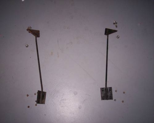
Photo 22: Lateral braces and fasteners.
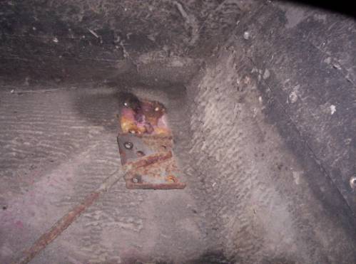
Photo 23:
Lateral brace extension inside wheel well, released from later brace
bolts.
G
Photo 24. Lateral brace connection to shock
tower.
24
Disconnect heater hoses
from inlet and outlet tubes behind the dash (almost visible in Photo 20).
25
Disconnect vacuum line
that leads from the intake manifold to the two vacuum reservoirs. Leave in
engine compartment.
26
Remove the gas tank
cross feed. It passes through the
frame. Disconnect from driver’s side
tank and pull up into body on passenger side.
27
Remove body
27.1
Place 4’ 2X4’s under
the body sills, running the length of the body.
27.2
Slowly jack each side a
few inches, alternating until the body is 4” off the frame.
27.3
Put 10’ 2X4’s under the
body, across the frame, at the frame mounting points, front and back. See Photo 25. 2X4’s must be on edge to support body weight.
27.4
Fasten 2X4’s to body
with lag bolts and fender washers, through existing frame mounting holes (two
front, two back), so body can not slip off 2X4’s when lifted.
27.5
Get 6-8 helpers. Body will have to be raised over engine, so
lifters have to be strong enough to raise to shoulder height.
27.6
Lift body and place on
cart. See Photo 26 for cart
design. Next time user bigger wheels.
27.7
Remove 2X4’s and save
for replacing the body.
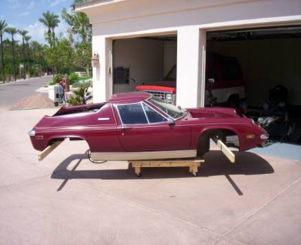
Photo 25. 2X4 beams are located under primary frame
mounting points on body and attached with lag bolts.
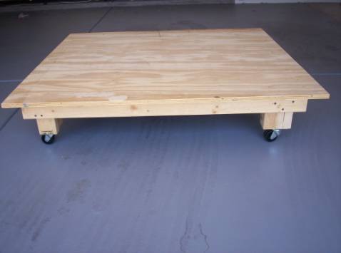
Photo 26. Cart is 3/4” plywood and 2X4’s.