Temperature gauge
| Temperature (C/F) 1 | Voltage (volts) 2 | Current (ma) 3 | Sender Resistance (Ohms) 4 | Sender Voltage 5 |
| 70/158 | 3.05 | 51.3 | 135.5 | 6.95 |
| 90/194 | 4.31 | 72.2 | 78.8 | 5.69 |
| 100/212 | 5.15 | 85.7 | 56.6 | 4.85 |
| 130/266 | 6.55 | 107.8 | 32.0 | 3.45 |
Oil Pressure Gauge
| Pressure (psi) 1 | Voltage (volts) 2 | Current (ma) 3 | Sender Resistance (Ohms) 4 | Sender Voltage 5 |
| 25 | 3.36 | 55 | 120.8 | 6.64 |
| 50 | 5.07 | 81.8 | 60.3 | 4.93 |
| 75 | 6.46 | 102.9 | 34.4 | 3.54 |
| 100 | 7.13 | 114.3 | 25.1 | 2.87 |
Fuel Gauge
| Level | Voltage (volts) 2 | Current (ma) 3 | Sender Resistance (Ohms) 4 | Sender Voltage 5 |
| 1/4 | 2.13 | 31.7 | 248 | 7.87 |
| 1/2 | 4.24 | 64.4 | 89.4 | 5.76 |
| 3/4 | 6.44 | 94.9 | 37.5 | 3.56 |
| f | 6.98 | 111 | 27.2 | 3.02 |
Errors from Poor Voltage Stabilization
(shows effect of increase
of voltage on gauge reading - sender held constant)
| Water Temp (C) | Oil Pressure (psi) | Fuel | Voltage |
| 90 | 50 | 1/2 | 10 |
| 97 | 60 | >1/2 | 11 |
| 100 | 75 | >1/2 | 12 |
| 110 | 85 | 2/3 | 13 |
| 120 | 95 | >2/3 | 14 |
| 128 | 105 | 3/4 | 15 |
The instrument panel stabilized voltage is supposed to be 10v. The above chart shows what will happen if the voltage is not stabilized. If, for example, the voltage is allowed to rise to 14v the water temperature gauge will indicate 120 degrees instead of the actual 90 degrees. It is quite possible for the voltage to rise into the 14 volt range above 3,000 rpm. The oil pressure gauge was done just for academics. For some reason, Lotus never connected it to the voltage stabilizer. As far as I know, all TC's use a mechanical oil pressure gauge so the above only applies to the S1/S2.
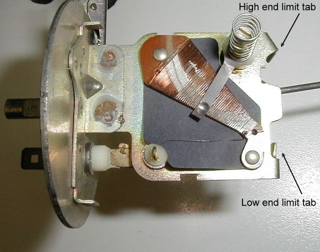
I checked the resistance range of a brand new, never used S2 fuel sender and found that it goes from 14.3 ohms to 245.3 ohms within the mechanical limits of the float arm. This fits rather well with the resistance range in the table above. However, it does look like readings below 1/4 tank would be a problem. The total internal resistance is about 260 ohms. This means that the mechanical stop is blocking off access to an additional 15 ohms. By bending one of the limit arms, increased range at the low end could be acheived.
Voltage and resistance measurements were made with a Fluke 8600A digital multimeter. Power was supplied by a Heath IP-27 regulated power supply. The voltage was set to 10 volts +- 5mv. Current values were calculated. The meters used were in excellent condition and taken from my 1970 S2. I hope this means that my measurements are valid for all Lotus gauges (including TC's). Without a larger sampling or access to original design specs, I guess this will have to suffice. When I get new senders, I'll run calibration checks on them and publish what I find on this page.
Would you like to see just how a Lotus gauge works?
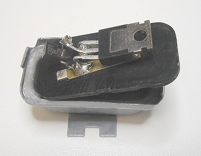
Electronic Regulator
There are plans for an electronic
regulator in files on the Yahoo Groups site. Here's a
picture of
the one I made. I gutted the original parts and installed the new electronic
regulator and capacitor on the backing plate. Once closed up and reinstalled
you'll never know. The parts I used are:
I recently obtained a new radiator thermal switch. I tested the switch for open/close temperatures. I averaged the readings over three tries and got the following:
| Contacts close above | Contacts open below |
| 186 F (85.5 C) | 181 F (82.8 C) |
1 - The unlabeled marks on the meter faces are
interpolated (i.e., 70 and 100 degrees and 25 and 75lbs).
2 - Voltage across meter terminals for the specified indication.
3 - Current through meter for the specified indication.
4 - Resistance of sender or transducer needed to cause
the specified gauge reading.
5 - Voltage measured from
sender to ground.
Last update: 26 Mar. 2004